EN
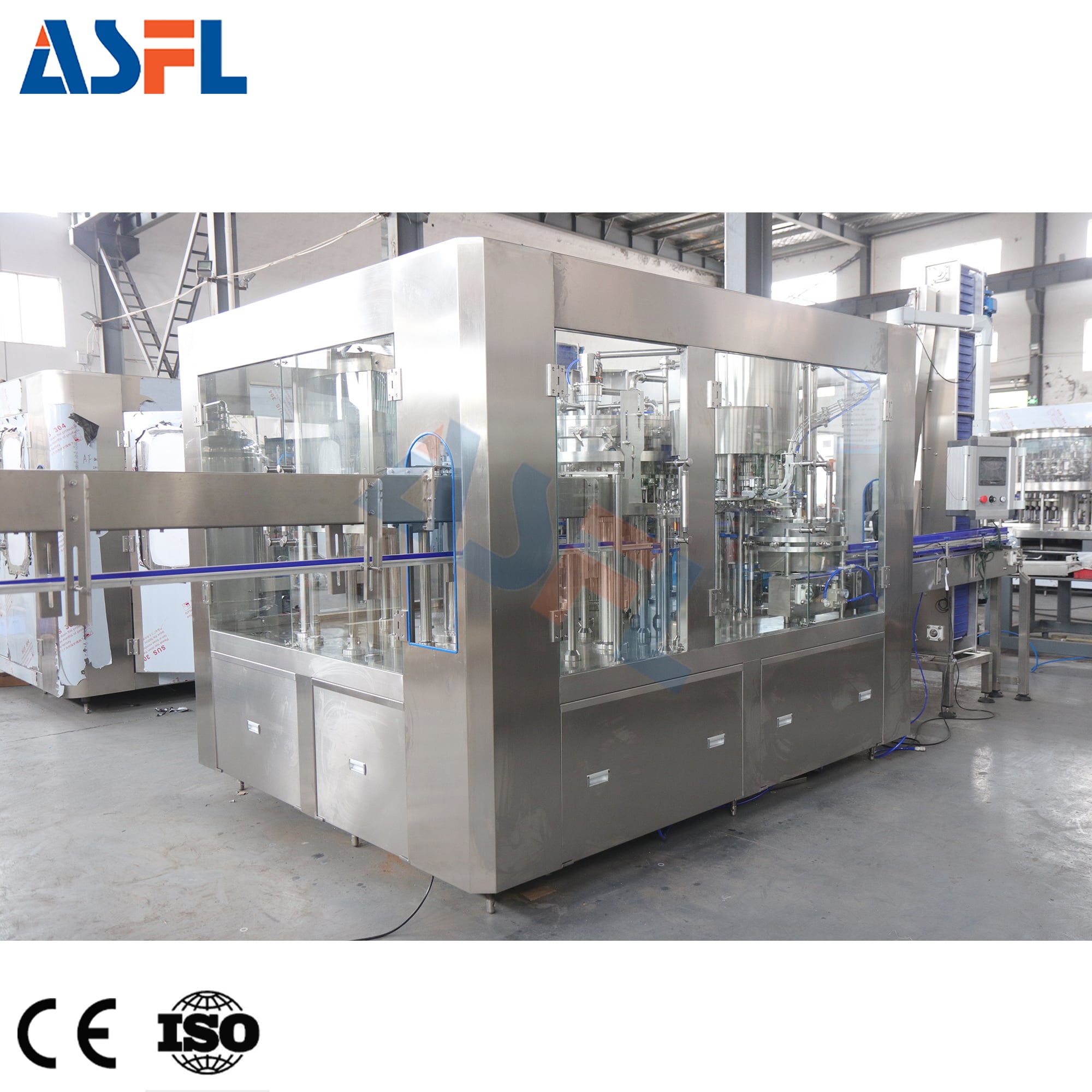
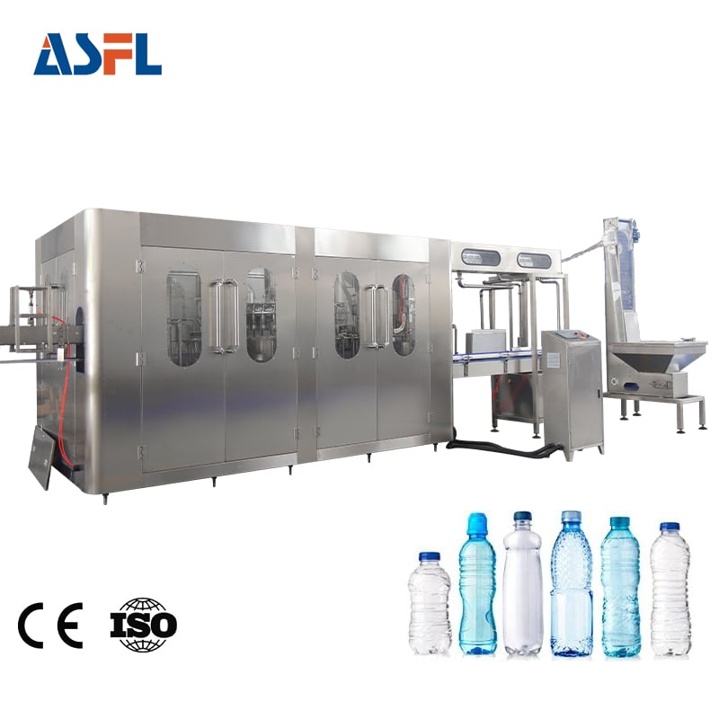
An inline bottle filling machine does not operate as an isolated island. It sits between bottle handling, product supply, cap handling, inspection, and discharge equipment, so stable output depends on how each handoff is designed. From a production-line engineering perspective, the useful question is not simply whether the filler can reach a stated speed. It is whether bottles, liquid, caps, and controls arrive at the right condition and leave without creating a new bottleneck.
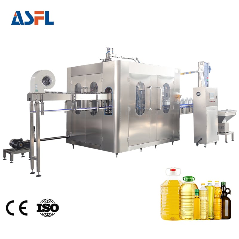
That distinction matters for water-like liquids, viscous products, and an oil bottle filling machine alike. Their process details differ, but every line needs predictable spacing, stable container positioning, compatible filling conditions, and a downstream path that can accept filled bottles. A practical integration plan views these as linked operating conditions rather than as separate purchase specifications.
Start with the line as a connected flow
An inline bottle filling machine typically receives empty bottles from an infeed conveyor or bottle unscrambler. The bottles are guided into a controlled pitch, presented to the filling nozzles, then released toward capping, labeling, coding, inspection, and packing. Seamless connection comes from aligning mechanical transfer, product delivery, and control handoff at every handoff.
First map the path of the bottle and the path of the liquid. Bottle travel involves conveyor width, guide-rail position, transfer plates, neck or body support, and accumulation space. Product delivery involves the supply tank, pump or gravity feed, sanitary piping where required, valves, and return or recirculation arrangements. A change in either path can affect fill accuracy, foam behavior, or the timing of the next station.
It is also worth mapping the information path. Sensors may signal bottle presence, low product level, cap shortage, jam conditions, or a stopped downstream conveyor. The inline bottle filling machine needs an agreed response to those signals: pause safely, hold bottles at the infeed, clear a discharge area, or resume in sequence. Without that logic, a small interruption after filling can become a queue of uncapped containers.
Coordinate the upstream section before focusing on filling
Bottle supply and infeed control
Upstream equipment should deliver bottles at a stable orientation and interval. An unscrambler, air conveyor, rinse station, or simple belt conveyor may be involved, depending on the package and process. At this handoff, confirm bottle diameter, height range, base stability, neck geometry, and the acceptable guide-rail setting. A bottle that rocks or rotates at the infeed can affect nozzle alignment even when the filling section itself is correctly adjusted.
Conveyor rhythm can amplify variation from the earlier section. If bottles bunch together, arrive with inconsistent gaps, or encounter a poorly aligned transfer plate, the filler may see missing bottles or uneven dwell time. For that reason, line engineers usually verify bottle flow at normal operating conditions rather than judging this handoff only while the conveyor is running empty.
Product supply as a filling handoff
Liquid delivery must match the chosen filling principle and the product’s actual behavior. Viscosity, entrained air, temperature variation, and foaming tendency can change how a product reaches the nozzle. For an oil bottle filling machine, the product supply arrangement should be assessed with the intended oil, bottle, and fill volume instead of relying on a generic liquid assumption. Stable supply pressure or head, appropriate pipe routing, and a sensible start-up procedure help the filler repeat its cycle under real conditions.
At this point, a production team should ask for a test plan. Rather than accepting a broad performance statement, define the bottle samples, product condition, target fill level, start-and-stop sequence, and observation points. The test can show whether the upstream supply remains stable while the line accelerates, pauses, and resumes.
Make the filling-to-capping handoff deliberate
After filling, the inline bottle filling machine hands a bottle with an open neck to the capping section. This short transfer is critical because spillage, bottle instability, or product on the neck can affect cap placement and torque consistency. The filler and capper should therefore be reviewed as one operating zone, even if they are supplied as separate modules.
Check the exit conveyor speed, guide-rail transition, and available spacing before the capper. If the filler discharges faster than the capper can accept bottles, accumulation may develop in the most sensitive area of the line. Conversely, if the capper repeatedly starves, the source may be upstream pitch control rather than cap delivery. Observing both stations together is more informative than adjusting either one in isolation.
Communication signals should also be defined. A downstream stop may require the filler to stop admitting new bottles before uncapped bottles accumulate. Cap shortage, rejected bottles, or a jam signal should have a clear stop-and-restart sequence. The aim is controlled recovery, not merely a fast restart.
Plan downstream capacity and inspection around the real output
Downstream equipment may include cap inspection, labelers, date coders, checkweighers, leak detection, case packing, or pallet handling. Each device has its own speed range and buffer requirement. An inline bottle filling machine connects smoothly when the overall line has a reasonable capacity balance, not when one module is selected only for its peak rate.
Accumulation conveyors can provide useful separation between stations, but they do not solve every mismatch. The line still needs rules for when accumulation is allowed, where bottle pressure must be avoided, and how equipment will respond when an inspection device rejects a container. A short review of reject paths and sensor placement often reveals issues before commissioning.
For an oil bottle filling machine, downstream cleanliness deserves equal attention. Small drips or neck contamination can travel into capping, labeling, and packing. Confirm where operators will inspect the bottle finish, how transfer surfaces are cleaned, and whether the discharge layout leaves practical access for routine checks.
Use controls and changeover settings as the common language
Mechanical compatibility is only part of seamless connection. The inline bottle filling machine must share a workable control philosophy with the surrounding equipment. Establish common conventions for line-ready signals, fault signals, emergency stops, speed references, and restart permissions. During installation, document which device leads the line speed and which devices follow it.
Changeover is another coordinated handoff. Bottle guides, nozzle height, conveyor settings, capper parts, labeler settings, and inspection recipes should be reviewed together. A line can appear compatible for one bottle format yet lose stability after a format change if only the filler recipe is updated. Breaking the changeover into measurable steps makes the risk visible and easier to improve.
A commissioning checklist for seamless operation
- Run empty bottles from the upstream source through the filler and capper to observe spacing, alignment, and transfer behavior.
- Verify the product supply with the intended liquid condition, including start, stop, and restart behavior.
- Confirm that the inline bottle filling machine reacts predictably to downstream stop, low-cap, and jam signals.
- Observe filled bottles at the capping handoff for stability, neck cleanliness, and adequate spacing.
- Test downstream accumulation and reject handling before accepting sustained production output.
- Record the settings and acceptance conditions for each bottle and product combination.
Choose handoffs before adding capacity
A well-coordinated inline bottle filling machine can support a smoother packaging flow because its upstream and downstream relationships have been specified, tested, and documented. The practical path is to begin with bottle and liquid conditions, then verify transfers, signals, capping coordination, and downstream capacity as a connected sequence.
In other words, higher speed is only one part of the decision. A line that maintains bottle control, stable product delivery, and orderly recovery from interruptions is usually easier to operate and validate. Before finalizing a configuration, use representative containers and product conditions to confirm each handoff across the full packaging route.

 Hot News