EN

What Safety Protection Settings Must an Automatic Liquid Filling and Capping Machine Equip?
An automatic liquid filling and capping machine should be specified as a guarded production system, not merely as a filler with a capper attached. Filling nozzles, bottle conveyors, cap feeders, spindle or chuck cappers, pneumatic cylinders, and electrical controls create different hazards at different moments in the cycle. The practical question is therefore not “does it have a safety guard?” but “which hazard is controlled, how is access detected, and how is the safe state verified?”
From a packaging-line engineering perspective, a practical starting point is to map the material path and operator access: infeed, bottle positioning, filling, cap delivery, capping, discharge, cleaning, and maintenance. The settings below form a useful acceptance checklist for an automatic liquid filling and capping machine. Final safeguards must be selected through a documented risk assessment and checked against the regulations that apply where the machine will operate.
Start with a risk assessment for the whole filling-and-capping cell
A liquid line is rarely hazardous in just one place. An operator may be exposed to pinch points at guide rails, moving bottles at star wheels, descending nozzles, rotating capper heads, accumulated air pressure, hot product lines, chemical residues, or unexpected restart after a jam is cleared. Review normal production, changeover, clearing, cleaning, adjustment, fault recovery, and maintenance separately. A safeguard that is suitable while bottles are running may not protect a technician inside a guarded zone.
For U.S. installations, OSHA 29 CFR 1910.212 identifies point-of-operation hazards, ingoing nip points, and rotating parts as hazards that require machine guarding. That is a useful baseline, but it does not replace the machine-specific risk assessment, applicable electrical rules, or the customer’s site procedures.
1. Physical guards around pinch points and rotating capping parts
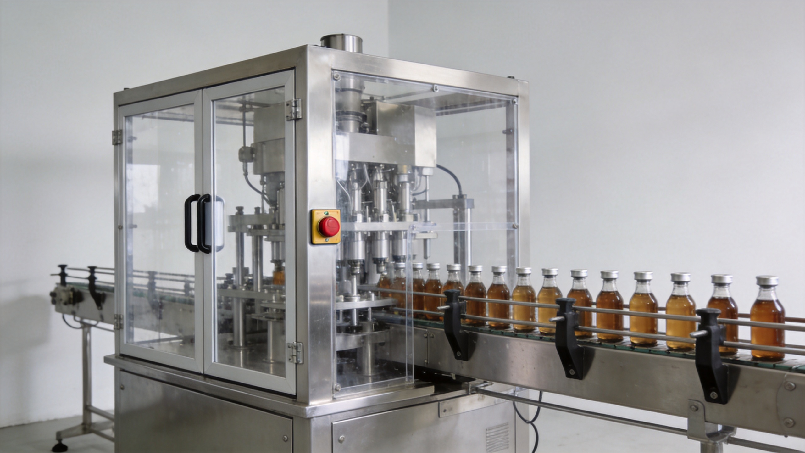
Fixed guards should prevent routine contact with exposed rotating capper spindles, chucks, belts, gears, sprockets, chain drives, star wheels, and accessible conveyor transfer points. The guard should be rigid enough for its environment, secured so that it cannot be casually removed, and designed without openings that permit hands to reach the hazard.
Pay special attention to the transition between the filler and capper. Bottle neck guides, cap chutes, tightening heads, and discharge conveyors often sit close together. Guarding should cover the actual reach-in path, including where a hand might follow a fallen cap or a tipped bottle. An automatic liquid filling and capping machine also needs enough access for sanitation and inspection; that access should be managed through safeguarded doors rather than through large unprotected openings.
2. Interlocked access doors and safety-rated guard switches
Where an operator must open a panel for routine clearing, cleaning, or changeover, use interlocked movable guards. Opening the guard should send the machine to a safe state before a person can reach the hazardous motion. The design must account for run-down: a rotating capper or moving conveyor can remain hazardous after the stop command. If access is possible before motion stops, a guard-locking arrangement or another validated protective measure may be needed.
Specify the behavior clearly in the control narrative: which motions stop, whether pneumatic energy is vented or held, whether product flow is stopped, and what is required before restart. A simple door switch that only removes a run signal may be inadequate if motion can coast, stored energy remains, or an automatic cycle can resume unexpectedly.
3. Emergency-stop devices placed at real intervention points
Emergency-stop devices should be readily reachable from normal operating and intervention positions: the operator panel, infeed, filling zone, capping zone, and discharge where appropriate. An emergency stop is a supplementary protective measure, not a replacement for guards or interlocks. It should stop hazardous motion promptly and require deliberate reset; reset alone should not restart production.
During factory acceptance testing, ask the supplier to demonstrate each E-stop with the line at its intended operating condition. Record what stops, what remains energized, the time to a safe state, and the reset/restart sequence. This turns an apparently simple button into a verifiable acceptance item.
4. Safety control functions for automatic restart prevention
A safe control design prevents an automatic liquid filling and capping machine from restarting merely because power returns, a guard closes, or an emergency stop is reset. Restart should require a conscious start action after the system confirms that guards are closed, faults are cleared, and the operating area is safe. Where a jam-clear or manual mode is required, use a deliberately selected mode with limited, supervised movement rather than leaving normal automatic operation enabled.
Define fault handling for common events: low caps, bottle jams, no-bottle/no-fill signals, conveyor overload, low air pressure, and sensor disagreement. Clear status messages and a reset procedure reduce the temptation to bypass safeguarding.
5. Energy isolation for cleaning, maintenance, and deeper fault recovery
Normal stop controls are not the same as energy isolation. Before servicing inside a hazard zone, the applicable lockout/tagout procedure should isolate electrical, pneumatic, hydraulic, thermal, and other stored energy sources. OSHA 29 CFR 1910.147 requires authorized employees to apply lockout or tagout devices to energy-isolating devices and verify isolation and deenergization before servicing or maintenance.
For a filling line, identify the main electrical disconnect, compressed-air isolation valve, any vacuum or product-pressure sources, and stored mechanical energy such as raised assemblies. Label these points and make them accessible without reaching into danger zones. If routine, minor tasks must occur during production, the site must determine whether a valid alternative protective method applies; do not assume that a stop button alone is enough.
6. Process-specific protection for liquid, chemical, and sanitation hazards
The liquid itself affects the safety design. Splash shields, drip containment, guarded hot surfaces, compatible seals, and drainage may be important for hot-fill products, corrosive liquids, foaming formulations, or aggressive cleaning chemicals. Food, pharmaceutical, and cosmetic applications also need a cleaning procedure that avoids exposing personnel to residual product or cleaning solution.
An automatic liquid filling machine may appear mechanically safe while still creating an exposure risk at nozzles, product tanks, hoses, or CIP connections. Document the medium, temperature, viscosity, cleaning chemistry, and required personal protective equipment before finalizing the machine configuration. Material compatibility and hygiene requirements should be verified with the process owner rather than inferred from a generic stainless-steel specification.
7. Sensors, alarms, and safe fault response
Production sensors are useful only when their failure response is understood. Bottle-present, cap-present, guard-open, low-air, pressure, level, and jam sensors should be checked for the action they trigger. Critical protective functions need appropriate diagnostics and validation; a sensor that merely displays an alarm while the mechanism continues to move does not control the underlying hazard.
- Verify that a guard-open signal inhibits hazardous automatic motion.
- Confirm that bottle jams stop or prevent the relevant movement before an operator reaches in.
- Test low-air and low-pressure conditions, especially where actuators could drift or lose holding force.
- Make manual/jog functions hold-to-run, limited-speed, or otherwise safeguarded as required by the risk assessment.
- Keep alarm history and intervention instructions available to trained staff.
8. Safe layout, training, and documented validation
Protection settings are only effective when the installation supports them. Leave working space for guarded-door access, cleaning tools, and lockout points. Prevent walkways from forcing people near conveyor pinch points. Train operators on normal stops, emergency stops, jam-clearing boundaries, and the prohibition on bypassing an interlock. Train authorized maintenance staff on the site energy-control procedure.
Before release, validate the safeguards using written tests. Test every guard opening, E-stop, restart condition, fault condition, manual mode, and energy-isolation point. Include the actual containers, caps, liquid behavior, and target line speed where possible.
A practical purchase and acceptance checklist
- List each hazard zone from infeed through discharge, including cleaning and maintenance access.
- Confirm fixed guards cover accessible nip points, rotating parts, and capper mechanisms.
- Confirm interlocked doors stop the correct hazardous motions and address run-down time.
- Check E-stop locations, reset behavior, and restart prevention under real operating conditions.
- Identify all electrical, pneumatic, hydraulic, thermal, and stored-energy isolation points.
- Review process-specific controls for product temperature, chemistry, splash, and sanitation.
- Witness documented tests with actual bottles, caps, and operating conditions before acceptance.
Conclusion
The essential protection package for an automatic liquid filling and capping machine combines physical guarding, interlocked access, emergency stops, restart prevention, safe fault handling, and verified energy isolation. The correct configuration depends on the product, container, capper design, layout, and local legal requirements. Treat each setting as a testable safety function—not a brochure feature—and require the supplier and site team to agree on the validation criteria before the line enters production.
 Hot News