EN

What safety interlock features should carbonated beverage bottling equipment include
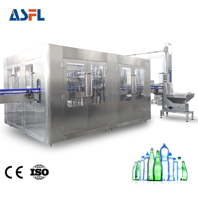
Carbonated beverage bottling equipment combines moving bottles, rotating turrets, conveyors, caps, pressurized product paths, and frequent operator access. That makes safety more than a perimeter fence around a filler. From a packaging-line engineering perspective, the right question is whether each access point, motion zone, and restart sequence behaves safely in the actual line layout.
A clear safety package for carbonated beverage bottling equipment should stop hazardous motion when access is opened, make the machine’s state visible, and require a deliberate, controlled restart. It should also distinguish between normal production stops and energy isolation for cleaning, jam clearing, adjustment, or maintenance. The details depend on the filler design, capper, bottle format, conveyor interfaces, and local regulations, so the final configuration should be verified through a documented risk assessment and site acceptance test.
Start with the hazards at each station
Before selecting switches or safety controllers, map the line by hazard rather than by machine name. On a typical carbonated bottling machine, accessible risks can include starwheel and conveyor pinch points, infeed and discharge transfers, rotating filler or capper components, cap-feed mechanisms, bottle breakage, and stored pneumatic or process pressure. The safest arrangement is rarely a single device repeated everywhere; it is a coordinated set of safeguards matched to the way people actually approach the equipment.
Walk the line during normal running, changeover, cleaning, and fault recovery. An area that seems inaccessible during production may become reachable when bottles accumulate, a guide rail is adjusted, or a cap chute is cleared. This may relate to bottle positioning, but it still needs confirmation during trial running. Record every guard, door, service panel, and intervention point before defining the interlock logic.
Core interlock features to specify
Interlocked movable guards and access doors
Use monitored interlocks on guards that provide access to hazardous movement. Opening a relevant guard should issue the required safe-stop command for the associated zone, while the control system should recognize the guard-open condition. OSHA’s general machine-guarding rule gives a useful principle: an interlocked enclosure on a revolving container keeps the drive from operating unless the enclosure is in place. For a bottling line, the application must be engineered for the actual guarded motion and stopping behavior.
Specify the access point, the motion that must stop, the expected stopping time, and the feedback that confirms the machine is in a safe state. A door switch by itself is not the full requirement. The safety function must be designed and validated as a system, including guard mounting, wiring, controller logic, actuator alignment, and fault detection.
Guard locking where motion needs time to stop
Some guarded zones may coast after a stop command because of inertia or process conditions. In those cases, guard locking can keep the door closed until the hazardous function reaches a safe state. The release logic should be based on verified safe conditions, not simply a fixed delay that may be unsuitable after a fault or changed operating condition. ISO 14119 addresses interlocking devices associated with guards and highlights the need to reduce reasonably foreseeable defeat of interlocks.
For carbonated beverage bottling equipment, review whether rotation, conveyors, cap-feed drives, or pressurized functions remain hazardous after the command to stop. The interlock design should make bypassing inconvenient and visible to the maintenance and safety team, while still allowing practical cleaning and adjustment procedures.
Emergency-stop devices with a defined response
Emergency-stop devices should be reachable from normal operator positions and from locations where personnel may respond to a jam or abnormal condition. Their required behavior should be stated clearly: which drives stop, how the filler or capper reaches a safe state, what happens to bottle handling, and how the line indicates the cause. Emergency stop is a supplementary protective measure; it does not replace guarded access, routine stop controls, or a servicing procedure.
Include reset behavior in the specification. Resetting an emergency-stop circuit should acknowledge that the device has been restored, not cause automatic line motion. A separate start action should be required after the system has confirmed that guards are closed, relevant safety devices are healthy, and the area is ready for operation.
Restart inhibition and controlled start-up
Restart inhibition is particularly important after a guard opening, power recovery, emergency stop, or safety fault. A carbonated bottling machine should not resume simply because a door is closed or electrical power returns. Use a deliberate reset and start sequence, with a clear indication of the condition that is blocking operation. This gives operators a chance to check that bottles, tools, and personnel are clear of the zone.
Here it is useful to separate two issues: filling control is one, and safe access is another. Product level, CO₂-related process conditions, and bottle presence signals can support orderly operation, but they should not be treated as substitutes for a safety-rated access function.
Interlock the interfaces, not just the filler
Safety logic should cover handoff points between machines. The infeed conveyor, rinser if used, filler, capper, discharge conveyor, and accumulation section can create hazards at transfers even when each unit has its own guard. Define what happens if one module stops, a downstream zone is opened, or a bottle jam is detected. The response may be a safe stop of the affected zone, an upstream controlled stop, or a line stop, depending on the risk assessment and operating sequence.
Use status indicators and diagnostics that identify the zone, guard, or device responsible for the stop. During commissioning, a vague “safety fault” message can add downtime and encourage operators to search for shortcuts. Clear diagnostics support disciplined recovery without making unverified changes to safety devices.
Do not confuse interlocks with lockout/tagout
An interlock supports routine access under defined operating conditions. It is not a replacement for energy isolation during servicing or maintenance. OSHA 29 CFR 1910.147 requires authorized employees to verify that equipment has been isolated and deenergized before work begins, and its guidance addresses the control of stored or residual energy. On carbonated beverage bottling equipment, that review can include electrical, pneumatic, mechanical, and process-pressure sources.
Specify isolation points, lockable devices, pressure-release steps, verification methods, and responsibilities in the line documentation. The practical test is whether a technician can identify every relevant energy source and confirm that it is in a safe condition before entering or working in a hazardous area.
Commissioning checklist for the safety function
- Open each interlocked guard during the applicable operating state and verify the documented safe response.
- Confirm that hazardous motion has stopped before any guard-lock release occurs where guard locking is required.
- Test that closing a guard, restoring power, or resetting an emergency stop does not initiate motion by itself.
- Verify restart requires a deliberate start command and that the line status makes the blocking condition understandable.
- Check upstream and downstream behavior at conveyor transfers, bottle jams, and module stops.
- Review bypass, override, and maintenance modes with controlled authorization, indication, and documented procedures.
- Validate energy-isolation steps separately from normal interlock tests before maintenance work is authorized.
How to write the safety requirement
Put the safety function in the purchase specification for carbonated beverage bottling equipment, rather than leaving it as a general request for guarding. For each guarded zone in the carbonated beverage bottling equipment, identify the access device, the hazardous motion, the required stop action, and the reset condition. This makes reviews of carbonated beverage bottling equipment more consistent across layout changes and format options.
For a carbonated bottling machine, ask the supplier to show the safety circuit description and the validation tests for every interlocked door. The same request should cover the carbonated beverage bottling equipment interfaces at the infeed, filler, capper, and discharge. During acceptance, test the documented response on the actual carbonated beverage bottling equipment, not only on a control-screen simulation.
Maintenance teams should receive the isolation procedure together with the carbonated beverage bottling equipment manual. A carbonated bottling machine needs an equally clear boundary between a production interlock and a locked, verified maintenance condition. That distinction helps make the safety requirements for carbonated beverage bottling equipment actionable after installation.
Turn safety requirements into a supplier-ready specification
When discussing carbonated beverage bottling equipment with a supplier, provide the bottle sizes, target output, beverage characteristics, layout, utility conditions, cleaning approach, and local machine-safety expectations. Then request a zone-by-zone safety description: guard locations, interlock type, guard-locking conditions, emergency-stop coverage, restart logic, safety diagnostics, and the commissioning evidence to be supplied.
Speed is only one part of the decision. A line that can be operated, cleaned, changed over, and recovered with clear safeguards is easier to evaluate over its working life. This article provides a decision framework; the final safety architecture should be confirmed against the actual machine, installed line, and applicable regulations.

 Hot News