EN

Technical Audit of CIP Risk Factors in Juice Bottling Operations
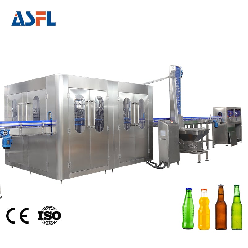
Ensuring complete microbiological safety in high-acid and low-acid juice packaging demands absolute control over sanitation fluid dynamics. In any commercial juice bottle filling and sealing machine, the Clean-In-Place (CIP) circuit serves as the primary barrier against biofouling, mold spore accumulation, and cross-batch contamination. Fruit juices contain sugars, pulp fibers, and organic acids that create stubborn foulants inside pipe manifolds and filling valves. When mechanical design flaws exist in the CIP loop, routine automated chemical flushes fail to sanitize critical product contact zones.
Identifying specific CIP cleaning design risk points allows processing engineers to transition from reactive troubleshooting to proactive sanitary design. Under international frameworks such as EHEDG Guidelines and FDA 21 CFR Part 114, liquid packaging machinery must achieve complete surface contact with sanitizing agents. A failure to identify and address hidden risk points inside a juice bottle filling and sealing machine results in hidden biofilm matrices, compromised shelf stability, and costly product recalls.
Mechanical Dead Legs and Pipe Geometry Vulnerabilities
The most pervasive physical risk point in any automated liquid processing circuit is improper pipe geometry. Dead legs occur where auxiliary branches, sensor pockets, or bypass lines divert from the main cleaning flow path. In a juice bottle filling and sealing machine, fluid stagnation inside these branches severely degrades CIP cleaning efficiency.
Key geometry-related risk points include:
-
Extended Branch Ratios: Pipe branches exceeding an L/D ratio of 1.5, where branch length L is greater than 1.5 times internal diameter D.
-
Downward Traps and Low Points: Pipeline paths lacking a continuous self-draining slope of at least 1.5 degrees, causing chemical pooling.
-
Sudden Diameter Expansions: Pipeline transitions that cause sudden pressure drops, reducing fluid shear stress below threshold levels.
-
Non-Hygienic Gasket Crevices: Over-compressed or misaligned sanitary triclamp gaskets that protrude directly into the fluid flow path.
When cleaning fluids enter a dead leg, velocity drops toward zero, preventing the hydraulic shear forces necessary to dislodge pulp particulates. Planktonic microorganisms settle into these quiet zones, building protective layers that withstand standard thermal and chemical CIP sanitization routines.
Hydraulic Shear Stress and Velocity Failures
Chemical concentration alone cannot compensate for poor fluid mechanics. The mechanical action of CIP cleaning relies on generating sufficient turbulent wall shear stress to strip away organic soils from inner pipe boundaries. Within a multi-nozzle juice bottle filling and sealing machine, maintaining balanced hydraulic distribution across all filling valves represents a critical design challenge.
| CIP Hydraulic Parameter | Sub-Optimal Design Threshold | Validated Target Parameter | Impact on Sanitation Efficacy |
| Flow State (Reynolds Number) | Re less than 2,300 (Laminar Flow) | Re greater than 4,000 (Fully Turbulent) | Fails to create boundary shear forces |
| Linear Fluid Velocity | Below 1.2 meters per second | 1.5 to 2.1 meters per second | Inadequate mechanical soil stripping |
| Manifold Pressure Differential | Delta P greater than 0.8 bar across nozzles | Delta P under 0.2 bar uniform pressure | Causes uneven cleaning across filling heads |
| CIP Return Pump Velocity | Air-locked or intermittent return | Continuous negative pressure return | Causes chemical pooling in bottom manifolds |
If the supply manifold in a juice bottle filling and sealing machine fails to deliver uniform fluid velocity across every filling head, outer valves experience laminar flow conditions. Under laminar flow, a slow boundary layer remains attached to the pipe wall, insulating bacteria and pectin residues from hot caustic washes.
Valve Interface and Rotary Seal Contamination Risks
The mechanical interface inside rotary distribution manifolds and filling valve assemblies represents another major CIP cleaning design risk point. Because a juice bottle filling and sealing machine integrates moving mechanical components with sterile product lines, dynamic seals must withstand continuous mechanical wear while maintaining sanitary boundaries.
Critical mechanical seal risk points encompass:
-
Sliding Stem Valve Seals: Dynamic O-rings that roll over unpolished metal surfaces, trapping micro-amount of juice solids inside rubber grooves.
-
Rotary Manifold Ceramic Seals: Micro-cracks or score lines on ceramic seal faces that collect fruit sugars and resist CIP fluid flushing.
-
Diaphragm Valve Flex Points: Stress cracks along elastomeric diaphragms that harbor mold spores away from chemical contact.
-
Vent Tube Internal Channels: Narrow air-return pathways in gravity filling valves that restrict CIP flow, leading to incomplete nozzle cleaning.
Without specialized CIP cups that clamp over filling nozzles to create a closed loop during sanitation, sanitizing chemicals cannot back-flush through the vent tubes and filling orifices. This leaves critical product contact surfaces unsterilized prior to production runs.
Thermal Dissipation and Chemical Concentration Fluctuations
Automated CIP cycles depend on precise coordination between temperature, chemical strength, exposure time, and mechanical force. In large-scale packaging operations, thermal dissipation across uninsulated valve manifolds creates hidden cold spots inside the juice bottle filling and sealing machine.
Thermal and chemical risk points include:
-
Uninsulated CIP Headers: Radiative heat loss that drops caustic wash temperatures below 75 degrees Celsius at distant filling nozzles.
-
In-line Dilution Errors: Faulty chemical dosing pumps that allow caustic concentrations to fall below 1.5 percent or acid washes below 1.0 percent.
-
Temperature Sensor Placement: Resistance Temperature Detectors (RTDs) positioned only at the supply inlet rather than the coldest return line point.
-
Chemical Phase Separation: Inadequate intermediate water flushes that allow caustic and acid chemicals to neutralize each other inside the filling line.
When temperature drops below critical thresholds at the filling nozzles, saponification of pulp fats slows down dramatically, rendering hot alkaline washes ineffective against stubborn microbial colonies.
Automated CIP Control and Sensor Validation
Relying on manual valves or unvalidated automated timers introduces severe operational risk. Advanced filling line architectures utilize integrated PLC monitoring to verify that every phase of the CIP routine satisfies validated critical limits before commercial production starts.
Essential automation and monitoring protocols require:
-
Dual-Pass Conductivity Monitoring: Inline sensors installed at supply and return headers to verify complete chemical evacuation during final water rinsing.
-
Flow Switch Interlocks: Automated switches that halt the CIP program if fluid velocity falls below 1.5 meters per second.
-
Automated CIP Cup Engagement: Proximity sensors confirming that sanitary cleaning cups are sealed tightly against every filling nozzle.
-
Differential Pressure Transmitters: Real-time logging of line pressure to detect partial nozzle blockages during sanitation cycles.
Industry leaders such as ACE-FILLING address these complex engineering challenges by designing advanced liquid packaging systems with optimized internal geometry, electropolished 316L stainless steel surfaces, and fully automated CIP manifold integration. Equipment specifiers and plant engineers can explore high-efficiency machinery designs and technical specifications by visiting
Summary of CIP Risk Mitigation Principles
Eliminating risk points within the CIP cleaning design of a juice bottle filling and sealing machine requires a comprehensive engineering strategy:
-
Design Out Dead Legs: Maintain pipe branch L/D ratios below 1.5 and ensure self-draining slopes across all product headers.
-
Guarantee Turbulent Shear: Maintain linear fluid velocities between 1.5 and 2.1 meters per second to ensure Reynolds numbers exceed 4,000 across all valves.
-
Implement Closed-Loop CIP Cups: Utilize automated sanitary cups to flush filling valve orifices, vent tubes, and return channels.
-
Validate Thermal Baseline: Log temperature at the furthest CIP return line to guarantee minimum exposure above 80 degrees Celsius.
-
Deploy In-Line Sensors: Install dual conductivity and flow transmitters to automate pass/fail verification for every cleaning cycle.
By implementing these rigorous hygienic design standards, juice beverage manufacturers prevent microbial contamination, protect product shelf stability, and maintain flawless operational compliance.
 Hot News