EN

The Thermodynamics of Carbonation and Foam Formation in Beverage Packaging
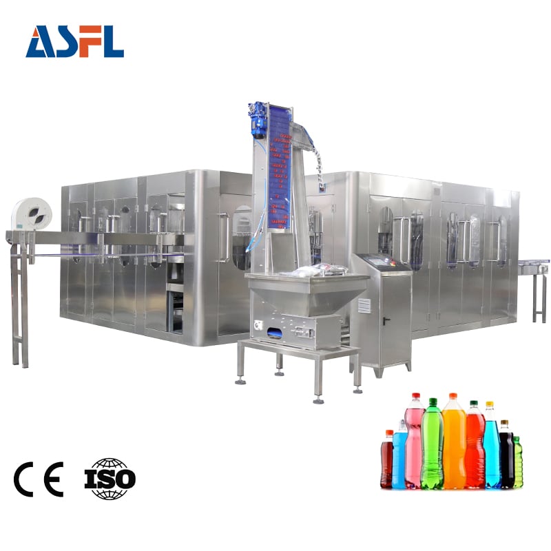
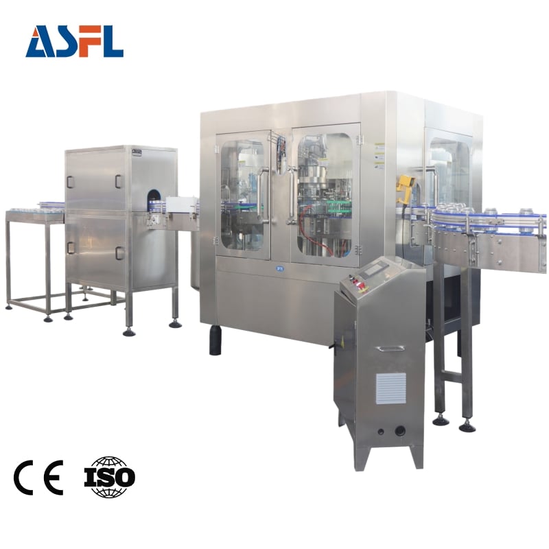
Carbonated soft drinks and sparkling beverages represent a high-speed, high-pressure packaging category where the physical chemistry of dissolved gas dictates mechanical design rules. When beverage processing plants integrate a high-speed soda filling and capping machine into their automated bottling lines, they immediately confront a complex thermodynamic challenge: dissolved carbon dioxide gas constantly strives to break out of liquid suspension whenever internal system pressures shift or mechanical shear forces are applied. Without a dedicated anti foaming technical design embedded directly into the filling valves, flow distributors, and pressure-equalization manifolds, rapid gas breakout triggers immediate flash foaming inside the bottle neck. This uncontrollable foam expansion ruins liquid volumetric accuracy, contaminates crown sealing surfaces, and causes catastrophic product yield losses across carbonated beverage bottling equipment during continuous operation.
The physical mechanics of foam expansion trace back to Henry Law, which dictates that the volume of gas dissolved in a liquid is directly proportional to the partial pressure of that gas above the liquid. Inside the holding bowl of a soda filling and capping machine, carbon dioxide is held under stable hyperbaric conditions, typically between 3.0 and 4.5 bar of pressure at lower temperatures around 4 to 8 degrees Celsius. However, as the liquid travels down through the filling nozzle into the empty container, any sudden pressure drop, micro-turbulence, or sharp mechanical direction change acts as an agitation trigger. Micro-bubbles form instantly around microscopic boundary layer irregularities, expanding exponentially as they rise to the surface. Effective beverage filling foam control requires engineered pressure matching, laminar liquid transport, and precise deceleration protocols at every phase of the transfer sequence to keep carbon dioxide fully dissolved until the bottle is permanently sealed.
Operational Liabilities Caused by Uncontrolled Foam Expansion
Operating carbonated packaging equipment without a purpose-built anti foaming technical design introduces severe structural and financial liabilities that severely impair plant Overall Equipment Effectiveness (OEE) and compromise finished product shelf life. When excessive foam overflows the container neck during or immediately following the filling stroke, sticky sugar syrup residues coat the exterior glass or PET bottle walls, contaminating downline transfer starwheels, bottle grippers, structural guide rails, and conveyor belts. Over time, these dried syrup deposits create abrasive friction, causing bottle tipping, mechanical jams, and frequent line stoppages for manual washdowns.
Beyond mechanical handling issues, foam overflow represents a direct threat to package seal integrity and long-term shelf stability. When foam rises into the bottle finish area, it deposits a thin film of liquid, pulp, or syrup directly onto the thread sealing land. During the capping phase, this fluid layer prevents the crown liner or plastic screw cap inner seal from making direct, dry contact with the container finish. Moisture and organic matter trapped beneath the seal can create micro-channel leak paths as the container undergoes ambient temperature swings in warehousing. Over weeks of storage, carbon dioxide continuously leaks through these microscopic channels while ambient oxygen ingresses into the headspace. The end result is a flat beverage, altered flavor profiles, premature product degradation, and high consumer rejection rates. Engineers at ACE-FILLING emphasize that embedding robust beverage filling foam control mechanisms into the core filler architecture is not merely an aesthetic choice, but an essential quality control wall that protects brand reputation and operational profitability.
Comparative Performance Matrix: Gravity Filling Versus Anti-Foaming Counter-Pressure Systems
To clearly demonstrate how specialized mechanical design mitigates carbonation loss, turbulence, and foam expansion, the technical comparative matrix below contrasts conventional open gravity filling setups with advanced counter-pressure systems incorporating a complete anti foaming technical design suite.
| Engineering Parameter | Conventional Gravity Filling Setup | Advanced Anti-Foaming Counter-Pressure System |
|---|---|---|
| Bottle Pressurization Mechanism | None (Filling occurs directly under ambient atmospheric pressure) | Dual-stage pre-evacuation and equalized carbon dioxide counter-pressurization |
| Liquid Flow Dynamics | High-turbulence central waterfall jet striking container base | Smooth, laminar wall-guided liquid descent via engineered radial umbrella deflectors |
| Pressure Venting & Snifting | Instantaneous atmospheric discharge causing violent gas flash | Multi-phase gradual snift control allowing entrained micro-bubbles to collapse |
| Active Foam Generation Rate | High (15% to 30% of internal container volume displaced by foam) | Ultra-low (Less than 2% active foam generated at peak operating speeds) |
| Container Sealing Integrity | Poor (Syrup and foam coat the thread finish and seal seating area) | Pristine (Dry, foam-free finish area ensures hermetic cap sealing) |
| Volumetric Filling Precision | Low (Variations in foam density cause fill height inconsistency) | Superior (Stable liquid meniscus yields consistent fill levels within 1 mm) |
Core Engineering Pillars of Effective Anti-Foaming Valve Architecture
Achieving predictable, zero-spill beverage filling foam control within a high-speed soda filling and capping machine demands sophisticated internal valve geometry and multi-stage fluid control. ACE-FILLING incorporates four foundational engineering mechanisms into every high-performance carbonated beverage bottling equipment installation to eliminate foam generation at the source:
-
Isobaric Pressure Equalization: Prior to opening the primary liquid seat, the filling valve charges the clean bottle with pressurized carbon dioxide gas matched exactly to the pressure inside the main filler bowl. By establishing absolute pressure equilibrium between the bowl and the bottle before liquid transfer commences, the system eliminates the pressure differential that causes instantaneous carbon dioxide flash boiling.
-
Radial Deflector Umbrellas and Wall-Guiding Flow Nozzles: Instead of allowing the beverage to cascade freely down the center of the bottle, engineered flow deflectors spread the incoming liquid into a thin, continuous film directed against the internal glass or PET sidewalls. This wall-guiding geometry converts turbulent kinetic energy into a smooth, laminar stream that glides down the interior contours without trapping air pockets or generating splash foam.
-
Dual-Stage Pre-Evacuation Vacuum Channels: For glass bottle packaging lines, removing ambient atmospheric air before pressurization is vital. The valve system draws a deep vacuum to purge oxygen and room air, replaces it with pure carbon dioxide, and draws a second vacuum phase. Eliminating air pockets reduces nucleation points and prevents oxidative degradation while suppressing foam generation during high-speed filling.
-
Multi-Phase Graduated Snift Decompression: Once the precise liquid fill level is reached, the liquid valve snaps shut, leaving a pressurized gas headspace above the liquid meniscus. Rather than venting this residual pressure instantly, the valve executes a controlled, multi-stage snifting sequence. By venting gas through micro-metering orifices in calibrated steps, the surface tension of the liquid stabilizes, allowing micro-bubbles to collapse safely back into the beverage body before the container lowers from the filling head.
Sanitary Engineering and Material Standards for Foam-Control Components
Integrating complex internal passages, vent tubes, and snift valves into a soda filling and capping machine must never compromise sanitary standards or cleanability. Modern carbonated packaging plants operate under stringent global hygiene frameworks, including US FDA food contact regulations and EHEDG hygienic design guidelines. All internal liquid channels, return gas tubes, and valve seats within the soda filling and capping machine are manufactured from ultra-low-carbon AISI 316L stainless steel, polished to a mirror surface roughness average (Ra) of less than 0.4 micrometers.
This ultra-smooth mechanical surface finish serves a dual purpose: it prevents microscopic product build-up that could host wild yeasts or spoilage bacteria, and it eliminates physical surface roughness that could trigger bubble nucleation during high-speed fluid movement. Furthermore, all elastomeric seals and diaphragm membranes are fabricated from food-grade EPDM or PTFE materials that resist chemical degradation during hot sodium hydroxide and peracetic acid Clean-in-Place (CIP) cycles. By maintaining smooth, crevice-free internal fluid pathways, the beverage filling foam control system delivers uncompromised biological purity alongside superior mechanical performance.
Preventive Maintenance Protocols for Long-Term Foam Control Performance
To sustain high filling accuracy and prevent gradual performance decay in carbonated beverage bottling equipment, plant maintenance teams must execute disciplined preventive maintenance routines focused specifically on anti-foaming subsystems:
-
Weekly Inspection of Centering Bell Seals: Examine rubber centering bells and bottle neck seals for micro-cracks, surface hardening, or mechanical distortion. Compromised seals cause pressure leaks during counter-pressurization, leading to instant foaming when the liquid valve opens.
-
Monthly Calibration of Pneumatic Snift Solenoids: Verify the actuation timing and exhaust orifice flow rates of the snift solenoid valves using PLC diagnostic routines. Clogged or sluggish snift exhaust lines prevent smooth gradual pressure release, resulting in sudden foam expansion during container discharge.
-
Bi-Monthly Verification of Vent Tube Straightness: Inspect internal gas return vent tubes for physical misalignment or micro-bending caused by bottle jams. Bent vent tubes alter the liquid shut-off geometry, leading to fill height variation and increased turbulence.
-
Quarterly CIP Piping and Check Valve Overhauls: Dismantle and rebuild pressure-equalization check valves and vacuum manifold seals using genuine replacement kits from ACE-FILLING to guarantee air-tight operational integrity across all production shifts.
 Hot News