EN
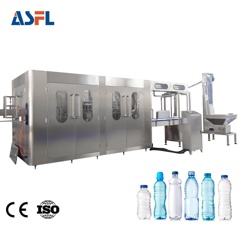
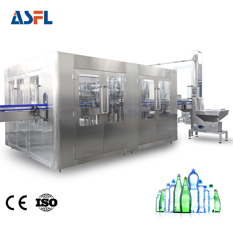
A beverage line can look crowded long before its building is full. Separate filler, capper, transfer conveyor, and accumulation points each need a frame, controls, guarding, and operator access. A monoblock filling and capping machine places the filling and cap-application functions in one coordinated machine zone. From a packaging-line engineering perspective, the practical question is not whether the machine is small in isolation. It is whether the integrated station reduces handoffs while leaving the people, cleaning tasks, and utilities around it workable.
Where separate stations consume usable floor area
A conventional arrangement often has a bottle conveyor leaving the filler, passing through an open transfer section, and entering a capping station. That transfer is more than a short length of conveyor. It can require bottle guidance, sensors, electrical routing, guarding, and a place for operators to clear a jam. In a tight beverage factory, each handoff expands the working envelope around the equipment.
With this integrated arrangement, the bottle typically moves between filling and capping inside a common frame or tightly coordinated enclosure. The layout may therefore need fewer separate support legs and fewer exposed transfer sections. An integrated filling-and-capping station can make it easier to keep the center of the line compact, especially where the infeed and discharge conveyors already have defined positions.
How an integrated process changes the layout
The most direct floor-space benefit of this arrangement is a shorter distance between two consecutive operations. Rather than reserving space for two independent machines and their connection, the design combines those operations around one bottle path. That can simplify the line drawing, cable routes, air connections, and guard boundaries. It can also reduce the number of places where bottles wait between operations.
However, a compact footprint is only one part of the calculation. The combined station still needs clearance for cap feeding, change parts, access doors, inspection, and maintenance. The useful comparison is the total working envelope: machine frame plus service space plus the conveyor path needed to connect it. A smaller frame that blocks cleaning or capper access is not a layout improvement in day-to-day production.
Why fewer transfer points matter on beverage lines
Every handoff between standalone stations is a point to align during installation and review during operation. Bottle stability, guide-rail changes, and speed coordination all deserve attention. By shortening the route between fill and cap, the integrated unit can reduce one set of handoff decisions. This does not remove the need to match the machine to bottle shape, liquid behavior, closure type, and target line pace. It does make the boundary between the two core operations easier to manage as one system.
For a beverage factory, that integrated boundary can help when planning a straight line, a compact U-shaped layout, or an upgrade inside an existing workshop. The combined unit should be drawn with the bottle unscrambler or rinser upstream and labeling, packing, or inspection equipment downstream. A combined unit works well in a compact plan when those neighboring connections remain straightforward rather than being forced into tight turns or inaccessible corners.
Space saving must preserve sanitation and service access
Food and beverage equipment must still be capable of cleaning and inspection. General sanitary-design guidance emphasizes accessible surfaces, while dairy-equipment guidance describes accessible and inspectable surfaces for CIP applications within its scope. The takeaway for layout planning is simple: do not measure only the cabinet outline. Leave room to open guards, inspect product-contact areas as applicable, reach conveyors, and perform the plant’s sanitation routine.
When reviewing the equipment, ask where an operator stands to replenish closures, where a technician reaches the filling area, and how waste or spills are handled. The integrated equipment saves floor area when those tasks occur from planned access sides rather than by creating extra aisles around separate machines. If the planned service side faces a wall or another conveyor, the theoretical footprint benefit can disappear.
Changeovers are part of the footprint decision
Beverage plants that run more than one bottle or cap format should treat changeover activity as part of layout, not as an afterthought. A monoblock may consolidate the location of bottle-handling and closure-related adjustments. That can shorten the walk between stations, but the team still needs space to bring change parts, verify guides, and check cap application.
Before selecting equipment, map the largest expected bottle, the closure-feeding method, and the operator movement during a format switch. Then confirm which components are adjusted at the filling section and which are adjusted at the capping section. The integrated arrangement is a better fit when these tasks can be completed from accessible sides without interrupting adjacent equipment.
A practical workshop-layout checklist
Use the following questions when assessing whether an integrated filling-and-capping unit can support a more efficient floor plan:
- What is the full operating envelope, including doors, guards, cap supply, and maintenance access?
- How will bottles enter and exit the integrated unit without unnecessary conveyor length or turns?
- Can sanitation staff reach the required surfaces and can operators inspect routine bottle-handling areas?
- Where will utilities, drains, controls, and safety clearances be located?
- Does the layout allow future labeling, inspection, or packing equipment to connect without rebuilding the center section?
Choose integration after verifying the real workflow
A monoblock filling and capping machine can free valuable workshop area because it brings filling and capping closer together and reduces an intermediate transfer zone. The benefit is strongest when the machine’s bottle path, closure supply, access sides, and upstream/downstream conveyors suit the factory’s actual workflow. In other words, first review the liquid and container conditions, then review the whole line connection. A properly planned integrated unit can make a beverage line easier to place, service, and expand without overstating what footprint integration alone can achieve.
 Hot News