EN
How to Plan Layout and Workflow for a New Water Filling Line
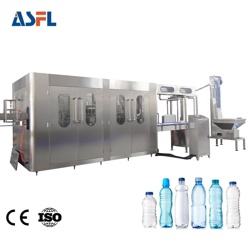
Planning a seamless plant layout and operational workflow design for a high-efficiency water filling line is one of the most critical steps when expanding beverage production. A poorly structured footprint leads to conveyor bottlenecks, excessive cross-contamination risks, and unnecessary labor costs. Whether installing a compact 3,000 bottle-per-hour system or a fully integrated 24,000 bottle-per-hour automated line, engineering the spatial allocation, material flow, and cleanroom partitioning requires rigorous attention to technical parameters. By following industry-tested line design frameworks and adhering to strict international manufacturing guidelines such as ISO 22000, FDA cGMP, and BRC food safety standards, plant managers can build an agile packaging facility that optimizes throughput and minimizes operational overhead.
Defining Space Allocation and Sanitary Zone Division
A high-performance water filling line requires clear spatial separation between raw bottle blow molding, clean filling zones, and secondary packaging areas. Physical segregation prevents airborne particulate contamination and thermal interference between heavy blow molding machines and wet bottling zones.
When structuring the plant footprint, the entire operation should be categorized into three distinct sanitary tiers:
-
Basic Clean Area (Secondary Packaging): Encompasses carton wrapping, palletizing, and finished product staging.
-
Medium Clean Area (Blow Molding & Conveying): Houses PET preform blow molders, air conveyor ducts, and preliminary bottle inspection units.
-
High-Clean Isolation Zone (Rinsing, Filling, Capping): Houses the primary monoblock water filling line under positive HEPA air pressure (Class 100/ISO 5 hygiene standards).
To avoid workflow cross-over, raw preforms and caps should enter from one side of the building, moving sequentially through purification, filling, labeling, and palletizing before exiting directly toward the warehouse dock. Designating dedicated maintenance pathways around the water bottling equipment ensures technicians can service mechanical drives and pumps without breaching pristine filling zones.
Optimizing Conveyor Logistics and Buffer Zones
In an automated liquid processing environment, line balance determines overall equipment effectiveness (OEE). Every water filling line consists of machines operating at slightly different mechanical speeds. If a downstream labeling machine or shrink wrapper experiences a brief momentary pause, an unbuffered upstream filling station will be forced to stop immediately, causing pressure surges and potential fill volume inaccuracies.
To maintain continuous workflow design, strategic buffer accumulation zones must be calculated between each core machine block:
-
Air Conveyor Buffer: Positioned between the PET blow molder and the rinsing/filling monoblock. It provides a 2-to-3 minute buffer of clean, air-floated empty bottles.
-
Slat Chain Accumulation Tables: Positioned after the capping turret and before the labeling machine. A multi-lane dynamic accumulation table offers 3 to 5 minutes of line buffering, absorbing micro-stoppages from secondary packaging systems without shutting down the water filling line.
Engineers at ACE-FILLING recommend sizing accumulation tables based on maximum line output. For instance, a system producing 10,000 bottles per hour requires approximately 15 to 20 meters of multi-track accumulation conveyor between the capping tower and the roll-fed labeling station to maintain frictionless production continuity.
Layout Configuration Analysis: Straight-Line vs. U-Shape vs. L-Shape
| Layout Topology | Spatial Requirement | Labor Allocation | Ideal Plant Application | Operational Strengths |
|
Straight-Line Layout |
Long, narrow floor space (60m+ length) |
Requires operators stationed at distinct points |
Extended industrial facilities with opposing docks |
Simplest conveyor logic, minimal transfer turns, easiest high-speed bottle handling |
|
U-Shape Layout |
Wide, square floor space |
Reduced footprint; 1-2 operators monitor start and finish |
Compact plants with unified receiving/shipping docks |
Centralized operator supervision, minimized fork-truck haul distances |
|
L-Shape Layout |
Corner space or multi-bay buildings |
Standard operator distribution across key modules |
Facilities with structural building columns or spatial constraints |
Flexible integration around existing structural walls, modular expansion options |
Utility Distribution and Hygiene Drainage Engineering
A resilient water filling line relies heavily on clean utility hookups. Electrical conduits, compressed air pipes, and pure water supply lines must be routed systematically overhead or through subterranean utility trenches to avoid ground-level tripping hazards and dust traps.
Key utility routing rules include:
-
Clean Compressed Air: High-pressure (30-40 bar) air lines for blow molding and low-pressure (6-8 bar) sterile oil-free air for pneumatic valve control must use 316L stainless steel piping.
-
Process Water Piping: Main feed lines connecting the reverse osmosis treatment plant to the water filling line monoblock must maintain continuous recirculation to prevent stagnant biofilm formation.
-
Hygiene Drainage: Trench drains featuring removable stainless steel basket strainers should run parallel to the filling and capping units, pitched at a minimum 1.5% gradient toward floor sinks.
Proper slope management prevents water pooling around water bottling equipment, ensuring compliance with strict FDA sanitary standards and maintaining cleanroom floor integrity.
Factory Acceptance Testing (FAT) and Validation Protocols
Before installing a full-scale water filling line on the plant floor, comprehensive validation must be conducted at the manufacturing facility. Factory Acceptance Testing (FAT) verifies that the physical footprint, conveyor synchronization, and workflow design match all operational specifications.
During FAT testing, engineers execute a series of stress trials:
-
Dry-Run Mechanical Alignment Test: Operating air conveyors and slat chains at 110% rated speed to verify container stability and zero bottle tipping.
-
Volumetric Dosing Calibration: Confirming fill level accuracy within +/- 1.0mm tolerance across all filling valves under varying line pressure conditions.
-
Emergency Line Stop Simulation: Testing sensor interlocks and buffer accumulation response during sudden downstream equipment stops.
By implementing pre-shipment FAT protocols, installation teams eliminate on-site layout adjustments, reducing facility commissioning time by up to 40 percent.
Successfully executing the layout planning and operational workflow design for a new water filling line demands a balance between spatial cleanroom zoning, smart conveyor buffering, and efficient utility distribution. By segregating hygiene zones, integrating dynamic accumulation tables, and choosing the right structural configuration—whether straight-line, U-shape, or L-shape—beverage producers achieve maximum line efficiency, minimal product waste, and full regulatory compliance. Partnering with experienced equipment manufacturers like ACE-FILLING ensures that your automated water bottling equipment is precisely tailored to your facility footprint, securing long-term operational success.
 Hot News